STM32F4X (Nucleo-F401RE, Carbon)
Flashing Overview
There are 2 main entry points for flashing STM32F4X SoCs, one using the ROM bootloader, and another by using the SWD debug port (which requires additional hardware).
Flashing using the ROM bootloader requires a special activation pattern, which can be triggered by using the BOOT0 pin.
The ROM bootloader supports flashing via USB (DFU), UART, I2C and SPI. You can read more about how to enable and use the ROM bootloader by checking the application note AN2606, page 109.
Nucleo-F401RE should be flashed over SWD, by using the STLINKv2.
Carbon should be flashed over USB DFU or UART, since there is no STLINKv2 support (unless when used with an external programmer).
Flashing Carbon
Flashing the STM32F401 chip
Entering DFU mode
Jumper between pin 1 and pin 6 of the ST SWD header (That will be the 3rd and 8th pin from the debug USB port).
Attention that the HW Rev 1.0 has an extra pin (7) for BOOT1. Make sure you are connecting to pin 6 (BOOT0).

v1.0 board shown with clips on reset and BOOT0 pins, enabling entering DFU mode.
Check the device is in DFU mode
Show the memory partitioning:
sudo dfu-util -l
dfu-util 0.8
Copyright 2005-2009 Weston Schmidt, Harald Welte and OpenMoko Inc.
Copyright 2010-2014 Tormod Volden and Stefan Schmidt
This program is Free Software and has ABSOLUTELY NO WARRANTY
Please report bugs to dfu-util@lists.gnumonks.org
Found DFU: [0483:df11] ver=2200, devnum=15, cfg=1, intf=0, alt=3, name="@Device Feature/0xFFFF0000/01*004 e", serial="3574364C3034"
Found DFU: [0483:df11] ver=2200, devnum=15, cfg=1, intf=0, alt=2, name="@OTP Memory /0x1FFF7800/01*512 e,01*016 e", serial="3574364C3034"
Found DFU: [0483:df11] ver=2200, devnum=15, cfg=1, intf=0, alt=1, name="@Option Bytes /0x1FFFC000/01*016 e", serial="3574364C3034"
Found DFU: [0483:df11] ver=2200, devnum=15, cfg=1, intf=0, alt=0, name="@Internal Flash /0x08000000/04*016Kg,01*064Kg,03*128Kg", serial="3574364C3034"
Found Runtime: [05ac:8290] ver=0104, devnum=2, cfg=1, intf=5, alt=0, name="UNKNOWN", serial="UNKNOWN"
You should see the following at your Linux host (dmesg):
usb 1-2.1: new full-speed USB device number 14 using xhci_hcd
usb 1-2.1: New USB device found, idVendor=0483, idProduct=df11
usb 1-2.1: New USB device strings: Mfr=1, Product=2, SerialNumber=3
usb 1-2.1: Product: STM32 BOOTLOADER
usb 1-2.1: Manufacturer: STMicroelectronics
usb 1-2.1: SerialNumber: 3574364C3034
Flash an application image in DFU
This tutorial uses the sample application shell $ZEPHYR_BASE/samples/shell.
To build the Zephyr kernel, enter:
cd $ZEPHYR_BASE
make -C samples/shell BOARD=carbon
Connect the micro-USB cable to the USB OTG Carbon port and to your computer.
Flash the application using dfu-util:
sudo dfu-util -d [0483:df11] -a 0 -D samples/shell/outdir/zephyr.bin -s 0x08000000
Connect the micro-USB cable to the USB UART (FTDI) port and to your computer.
Run your favorite terminal program to listen for output.
sudo screen /dev/<tty_device> 115200
# Replace <tty_device> with the port where the Carbon
# board can be found. For example, under Linux, /dev/ttyUSB0.
Remove the jumper, press the Reset button and you should see the output of shell application in your terminal.
Flashing the nRF51 chip on the Carbon
Use the Segger programmer
The Carbon has a nRF51 MCU connected to the STM32F401 MCU over SPI for Bluetooth LE communication. This MCU has to be programmed separately using the SWD header pins and a SWD programmer such as the Segger. There is a Zephyr port available for the nRF51 and we will use that for this project. So, Zephyr running on the STM32F4 will talk to Zephyr running on the nRF51 over SPI.
To flash the Carbon nRF51 MCU simply connect the 3V3, GND, CLK and DIO pins on the BLE header to the SWD programmer and supply power to the Carbon board. In the picture below, we’re using the nRF52 Development Kit that contains a built-in Segger to flash the Carbon’s nRF51 chip.

Firmware (Upstream compatible with SPI HCI Host)
Build and flash the nRF51 Zephyr SPI HCI firmware:
git clone -b master-upstream-dev https://github.com/Linaro/zephyr.git
cd zephyr
make -C samples/bluetooth/hci_spi/ CONF_FILE=96b_carbon_nrf51.conf BOARD=96b_carbon_nrf51
Flash the application using nrfjprog:
nrfjprog -f nrf51 --chiperase --reset --program samples/bluetooth/hci_spi/outdir/96b_carbon_nrf51/zephyr.hex
Flash the application using pyocd-flashtool:
pyocd-flashtool -t nrf51 -ce -f 120000 samples/bluetooth/hci_spi/outdir/96b_carbon_nrf51/zephyr.hex
Use a generic ST-Link-v2 programmer on the to program the NRF51 chip on the Carbon

Connecting a Carbon to an ST-Link-v2 programmer (https://www.amazon.com/Qunqi-ST-LINK-STLINK-debugger-programmer/dp/B016ZPNEYC)
Install openocd:
# Common dependencies
apt install pkg-config automake libtool

# openocd upstream repository
git clone git://git.code.sf.net/p/openocd/code openocd-code
cd openocd-code
./bootstrap
./configure
make
make install
Create a cfg file:
carbon-nrf51-stlink-v2.cfg
source [find interface/stlink-v2.cfg]
transport select hla_swd

set WORKAREASIZE 0x4000
source [find target/nrf51.cfg]
Run openocd & program binary:
openocd -f carbon-nrf51-stlink-v2.cfg -c "program /pathto/zephyr.hex verify exit"
Using the ST-Link-v2-1 on the Nucleo-F401RE to program the NRF51 chip on the Carbon
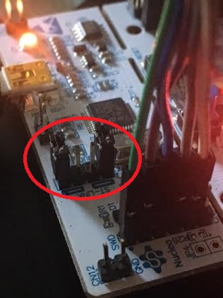
Open the jumpers on connector “CN2” as shown.
Install openocd:
# Common dependencies
apt install pkg-config automake libtool

# openocd upstream repository
git clone git://git.code.sf.net/p/openocd/code openocd-code
cd openocd-code
./bootstrap
./configure
make
make install
Create a cfg file:
carbon-nrf51-stlink-v2-1.cfg
source [find interface/stlink-v2-1.cfg]
transport select hla_swd

set WORKAREASIZE 0x4000
source [find target/nrf51.cfg]
Run openocd and program binary:
openocd -f carbon-nrf51-stlink-v2-1.cfg -c "program /pathto/zephyr.hex verify exit"
Flashing Nucleo-F401RE
Enabling ST-LINK
To use ST-LINK to program the STM32F401-RE SoC, you need to plug in the two jumpers on CN2 (ST-LINK).

Flashing with STLINKv2 (SWD)
This tutorial uses the sample application shell $ZEPHYR_BASE/samples/shell.
To build the Zephyr kernel, enter:
cd $ZEPHYR_BASE
make -C samples/shell BOARD=nucleo_f401re
Connect the micro-USB cable to the Nucleo USB port and to your computer.
Flash the application using openocd:
make -C samples/shell BOARD=nucleo_f401re flash
Run your favorite terminal program to listen for output.
sudo screen /dev/<tty_device> 115200
# Replace <tty_device> with the port where the
# Nucleo board can be found. For example, under Linux,
# /dev/ttyAMA0.
Press the Reset button and you should see the output of the shell application in your terminal.